Dynamic Applications can be configured to automatically create relationships between devices. For example, the Dynamic Applications in the VMware vSphere and NetApp PowerPacks are configured to create relationships between VMware Datastore component devices and their associated NetApp Volume component devices. Relationships created by Dynamic Applications are used and visualized by Skylar One in the same manner as relationships created by topology collection, Dynamic Component Mapping, and manually in the user interface.
There are three methods for configuring Dynamic Applications to automatically create relationships:
- A single configuration Dynamic Application that collects the unique identifier (UID) for a component device. When Skylar One polls a subscriber device and collects a UID value, and that UID value matches the UID for an existing component device in the same component tree as the subscriber device, Skylar One creates a relationship between the subscriber device and the component device.
- A single configuration Dynamic Application that collects the globally unique identifier (GUID) for a component device, typically a component device that is in a different component tree than the subscriber device. When Skylar One polls a subscriber device and collects a GUID value, and that GUID matches the GUID of an existing component device that is in a different component tree than the subscriber device, Skylar One creates a relationship between the subscriber device and the component device.
- A pair of configuration Dynamic Applications collect the same data. One of these Dynamic Applications is configured to define a unique identity for subscriber devices and also references the relationship. The other Dynamic Application defines the relationship and also references the unique identity. If each Dynamic Application collects the same value for unique identity and the same value for relationship, a relationship is created between the two subscriber devices. This type of relationship is described in the section Configuring Identity-based Relationships.
Use the following menu options to navigate the Skylar One user interface:
- To view a pop-out list of menu options, click the menu icon (
 ).
). - To view a page containing all of the menu options, click the Advanced menu icon (
 ).
).
Configuring Collection Objects for Relationships
To configure a collection object for the creation of relationships:
- Go to the Dynamic Applications Manager page (System > Manage > Dynamic Applications).
- Find the configuration Dynamic Application that you want to configure. Select its wrench icon (
 ). The Dynamic Applications Properties Editor page is displayed.
 - Select the tab. The Dynamic Applications | Collections Objects page is displayed.
- Select the wrench icon () for the collection object you want to edit.
- The Usage Type field specifies how this collection object is used to build relationships. The options in this field are:
- Standard. The collection object is not used to create relationships or designated as an index for the specified collection object group.
- Group Index. The collection object is configured as the index for the selected collection object Group. For more information about indexing, see the Indexing section. Additionally, if other collection objects in the same group are configured with a Usage Type of Identity Namespace or Relationship Namespace, Skylar One uses the collection object with a Usage Type of Group Index to define the unique identifier and create relationships between the subscribers of two related Dynamic Applications. See the Configuring Identity-based Relationships section for a description of how to implement this type of relationship.
- Identity Namespace. Skylar One uses the collection object to create relationships between the subscribers of two related Dynamic Applications. This collection object defines the identity portion of the relationship. If Skylar One collects this collection object from a device, Skylar One will make that device the child in a parent-child relationship. See the Configuring Identity-based Relationships section for a description of how to implement this type of relationship.
- Relationship Namespace. Skylar One uses this collection object to create relationships between the subscribers of two related Dynamic Applications. If Skylar One collects this collection object from a device, Skylar One will make that device the parent in a parent-child relationship. See the Configuring Identity-based Relationships section for a description of how to implement this type of relationship.
NOTE: Usage Type of Identity Namespace defines the child portion of an identity-based relationships. Usage Type of Relationship Namespace defines the parent portion of an identity-based relationships.
- GUID Relationship. When Skylar One collects a value for this collection object, and that value matches the GUID for a component device in the system, Skylar One creates a relationship between the subscriber device and the component device. The subscriber device will be the parent device and the component device will be the child device. The relationship will be labeled with the name of this collection object.
- Unique Identifier Relationship. When Skylar One collects a value for this collection object, and that value matches the unique identifier for a component device in the same component tree as the subscriber device, Skylar One creates a relationship between the subscriber device and the component device. The subscriber device will be the parent device and the component device will be the child device. The relationship will be labeled with the name of this collection object.
- GUID Relationship + Index. Skylar One uses this collection object to create relationships in the same manner as the GUID Relationship option. When Skylar One collects a value for this collection object, and that value matches the GUID for a component device in the system, Skylar One creates a relationship between the subscriber device and the component device. The subscriber device will be the parent device and the component device will be the child device. The relationship will be labeled with the name of this collection object. Additionally, the collection object is configured as the index for the specified collection object group.
- Unique Identifier + Index. Skylar One uses this collection object to create relationships in the same manner as the Unique Identifier Relationship option. When Skylar One collects a value for this collection object, and that value matches the unique identifier for a component device in the same component tree as the subscriber device, Skylar One creates a relationship between the subscriber device and the component device. The subscriber device will be the parent device and the component device will be the child device. The relationship will be labeled with the name of this collection object. Additionally, the collection object is configured as the index for the specified collection object group.
- Click .
Configuring Identity-Based Relationships
An identity-based relationship is created using a pair of Dynamic Applications:
- A Dynamic Application that defines a unique identity for subscriber devices. This Dynamic Application defines:
-
a unique ID for the device, using a collection object that usually has a Usage Type of Group Index.
-
the identity side of the relationship, using a collection object that usually has a Usage Type of Identity Namespace. The devices that subscribe to this Dynamic Application will be children in the parent-child relationship that is created using the unique identity.
NOTE: This identifier must be unique to this relationship, meaning no two subscribers of the same Dynamic Applicationshould collect the same identifier for the same relationship. However, both Dynamic Applicationsin the pair must collect the same identifier value for a relationship to be created.
- A Dynamic Application that defines the relationship for subscriber devices. This Dynamic Application defines:
-
a unique ID for the device, using a collection object that usually has a Usage Type of Group Index.
-
a relationship, using a collection object that usually has a Usage Type of Relationship Namespace. The devices that subscribe to this Dynamic Application will be parents in the parent-child relationship that is created using the unique identity.
A relationship is created when:
- both Dynamic Applications in a pair collect identical values for the unique identifier (the collection object with a Usage Type of Group Index.
- the value for the collection object that has a Usage Type of Identity Namespace is identical to the value for the collection object that has a Usage Type of Relationship Namespace.

To configure a pair of Dynamic Applications to create identity-based relationships, go to the Dynamic Applications Collection Objects page:
- In both Dynamic Applications, select the collection object that collects the identifier for the relationship. In the Usage Type field, select Group Index. Select a Group for the collection object. The Group should be the same in both Dynamic Applications.
- In the Dynamic Application that defines a unique identity for subscriber devices, select the collection object that collects the namespace for the relationship. In the Usage Type field, select Identity Namespace. For this collection object, select the same Group as the Group Index collection object.
- In the Dynamic Application that defines the relationship, select the collection object that collects the namespace for the relationship. In the Usage Type field, select one of the values that includes the text "Relationship". For this collection object, select the same Group as the Group Index collection object.
NOTE: The Identity Namespace and Relationship Namespace objects must return a value for each of the indexes returned by the Group Index object. Typically, the values at each index returned by the Identity Namespace and Relationship Namespace objects are equal.
NOTE: For an example of a Dynamic Application with an Identity-Based relationship,
Viewing a Map of Component Devices
The Component Map page allows you to view devices by root node and also view the relationships between root nodes, parent components, and child components. This map makes it easy to visualize and manage root nodes and their components.
NOTE: User accounts of type "user" can view only root nodes and device components that belong to their organization(s).
Skylar One uses Dynamic Applications to retrieve data from a management device and discover each entity managed by that management device. Skylar One then uses that retrieved data to create a device for each managed entity. In some cases, the managed entities are nested.
- In Skylar One, a managed entity is called a component device. A component device is an entity that runs under the control of a physical management device.
- In Skylar One, the root device is the physical device that manages one or more component devices.
- In Skylar One, a parent device is a device that has associated entities modeled as component devices. A parent device can be either a root device or another component device.
For example, in a Cisco UCS system, Skylar One might discover a physical server that hosts the UCS manager. Skylar One might discover a chassis as a component device. The chassis is a child device to the physical server; the physical server is the root device. Skylar One might also discover a blade as a component device that is part of the chassis. The blade is a child device to the chassis. The chassis is the parent device.
Skylar One automatically updates the Component Map as new component devices are discovered. Skylar One also updates each map with the latest status and event information.
NOTE: For a user of type User, you can view only root nodes and device components that belong to your organization(s).
Viewing a Component Map
You can view a component map from the Component Map page. To view a Component Map:
- Go to the Classic Maps page (Maps > Classic Maps).
- Expand the links for Device Maps > Components and then select a root node. The Device Component Map page appears and displays the map of the root node and its component devices.
Adding Devices from Another Component Tree to the Component Map
You can add a device from another component tree to the map of the current component device.
For example, suppose you have a UCS system. Suppose you are running an ESX server and VMs on one of the blades of the UCS system:
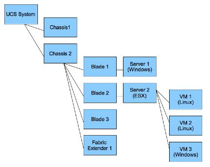
You can add the device where the ESX server resides to the map of the UCS system. To do this:
- Go to the Component Map page (Maps > Classic Maps > Device Maps > Components).
- Expand the list of maps. Find the component map to which you want to add a device.
- Select the button. Select the Add Dev icon (in the upper left).
- In the Device Browser modal page, select the root node you want to add to the component map. Select the button.
NOTE: When you complete these steps, the Skylar One system will automatically add all the child devices for the newly added node to the map.
- Select the button. Click on the parent device and then click on the newly added child device.
- The link you created is an Event Correlation Override link. If you want to manually define a parent device and child device for two devices that do not share a Layer-2 link, a Layer-3 link, a CDP link, an LLDP link, or a VMware relationship, you can create an Event Correlation Override link between the devices. Additionally, you can then define an event hierarchy for these devices.
- Select the button.
- Select the button to view the changes to the map.
Viewing Relationships Maps in the Organization View
The Organizational Map page allows you to view devices by organization. This makes it easy to visualize and manage devices in organizations. If devices in the organization include relationships created by Dynamic Applications, these relationships are displayed in the map. If devices in this organization include CDP, LLDP, layer-2, or layer-3 relationships, they are included in the map.
All elements, policies, events, tickets, and users in Skylar One are associated with an organization. An organization is a group for managing elements and user accounts. You can define organizations by geographic area, departments, types of devices, or any structure that works best for your needs. The minimum characteristics of an organization consist of:
- A unique name
- Users who are members of the organization
- Elements, such as devices, associated with the organization
Skylar One automatically updates the Organizational Maps as new devices are added to organizations and as new organizations are defined. Skylar One also updates each map with the latest status and event information.
To select an Organizational Map, go to the Classic Maps page (Maps > Classic Maps), expand the links for Device Maps > Organizational, and then select an organization. The Organizational Map page appears and displays a map of the selected organization and its devices.
Viewing an Organizational Map
You can view an organizational map from the Organizational Map page. To view an organizational map:
- Go to the Classic Maps page (Maps > Classic Maps).
- Expand the sections for Device Maps > Organizational, and then select an organization. The Organizational Map page appears and displays a map of the organization and its member devices:

- The search field at the top allows you to find one or more devices in the map. You can enter a string, and Skylar One will highlight only the devices that have a device name that matches the string.
- Each member device appears as an icon in the map.
- The Organizational Map page for an organization also displays the relationships between devices in the organization. This includes:
- Layer-2 devices and their clients
- Layer-3 devices and layer-2 devices
- Component devices and their parents, e.g. virtual machines and their hypervisors
- Network devices that use CDP (Cisco Discovery Protocol) and devices that are specified as neighbors in the CDP tables
- Network devices that use LLDP (Link Layer Discovery Protocol) and devices that are specified as neighbors in the CDP tables
- Device relationships created with Dynamic Applications
- Manually created parent-child relationships that affect event correlation
- When the map appears, you can view and reposition the components. The map can be edited and rearranged using drag-and-drop features. Devices can be repositioned for easier reading, if necessary.
- Mousing over a device displays its name, IP address, device type, and device category.
Viewing Relationships in Customized Maps
A customized map allows you to view the devices and links that are most important to you.
When you create a customized map, you are also creating a new device group (which appears in the Device Groups page). You can add devices and other sub-device groups to the new map, just as you would to a standard device group.
If Skylar One has information about the relationships between the devices in a customized map, Skylar One automatically includes the appropriate links in the customized map. Customized maps display every type of relationship data, which includes:
- Layer-2 devices and their clients
- Layer-3 devices and layer-2 devices
- Component devices and their parents, e.g. virtual machines and their hypervisors
- Network devices that use CDP (Cisco Discovery Protocol) and devices that are specified as neighbors in the CDP tables
- Network devices that use LLDP (Link Layer Discovery Protocol) and devices that are specified as neighbors in the LLDP tables
- Device relationships created with Dynamic Applications
- Manually created parent-child relationships that affect event correlation
Customized maps appear in the following sections:
- My Customized Maps. Personalized maps that you create.
- User Customized Maps. If you are a user of type "administrator", you can navigate to the maps in this section to view and edit all customized maps in Skylar One, even if the device group associated with the map was defined with the field Shared (visible to all users) set to no.
- Shared Customized Maps. If a customized map or device group is defined as "shared", you can view the maps in this section. The maps in Shared Customized Maps require the same Access Hooks and Access Keys as device groups. Depending upon the Access Keys assigned to your account, you might be able to edit Shared Customized Maps created by other users.
NOTE: If you create a device group from the Device Groups page and set the Visibility field to include Maps/Views, the device group will appear as a map in the Custom Device Group Map page (Maps > Classic Maps > My Customized Maps). If you set the Shared field to yes, the device group will appear for view by other users as a map in the Shared Customized Maps page (Maps > Classic Maps > Shared Customized Maps).
Viewing Relationships for a Single Device
You can view all links for a single device on the Relationships tab of the Device Investigator (or on the Device Relationships page in the Device Properties panel in the classic Skylar One user interface).
To view all links for a single device:
- Go to the Relationships tab of the Device Investigator. (Alternatively, in the classic Skylar One user interface, go to the Device Manager page (Devices > Classic Devices, or Registry > Devices > Device Manager in the classic user interface), click the wrench icon for a device () and click the tab in the Device Properties pane.) The Device Relationships page appears.
- The left pane of the Device Relationshipspage displays links to parent devices. The right pane of the Device Relationships page displays links to child devices. For each relationship, the Device Relationships page displays the following information:
- Type of relationship. Possible values are:
- Layer 2. Layer-2 devices and their clients.
- Layer 3. Layer-3 devices and layer-2 devices.
- VMware. Hypervisors and their virtual machines.
- CDP. Network devices that use CDP (Cisco Discovery Protocol) and devices that are specified as neighbors in CDP tables.
- LLDP. Network devices that use LLDP (Link Layer Discovery Protocol) and devices that are specified as neighbors in LLDP tables.
- Event Correlation. Relationships defined manually by users through the user interface.
- Component Mapping. Relationships defined using Dynamic Applications.
- Parent Device. The name of the parent device and a link to the Device Properties page for the parent device.
- Parent Interface. The name of the interface through which the parent device communicates with the child device and a link to the Interfaces Found page for the parent interface.
- Child Device. The name of the child device and a link to the Device Properties page for the child device.
- Child Interface. The name of the interface through which the child device communicates with the parent device and a link to the Interfaces Found page for the child interface.
NOTE: Clicking on a device reloads the Device Relationships page and makes the selected device the primary device.
The Device View page appears when a user clicks the Topology tab in the Device Reports panel. The Device View page displays a map of the device and all of the devices with which the device has relationships.
These relationships include:
- Layer-2 devices and their clients
- Layer-3 devices and Layer-2 devices
- Component devices and their parent devices. For example, virtual machines and their hypervisors and their virtual machines.
- Network devices that use CDP (Cisco Delivery Protocol) and devices that are specified as neighbors in CDP tables
- Links between network devices that use CDP (Cisco Discovery Protocol) and devices that are specified as neighbors in CDP tables
- Network devices that use LLDP (Link Layer Delivery Protocol) and devices that are specified as neighbors in LLDP tables
- Links between network devices that use LLDP (Link Layer Discovery Protocol) and devices that are specified as neighbors in LLDP tables
- Device relationships between root devices, parent devices, and component devices (Component Mapping)
- Device relationships created with Dynamic Applications
- Manually created parent-child relationships that affect event correlation
NOTE: Double-clicking on a device reloads the Device View page and makes the selected device the primary device.
For details on the toolbars that appear in this page,