![]()
This
Upon installation, SL1 appliances are automatically licensed for 30 days. During these 30 days, you can perform the steps to obtain a permanent license from ScienceLogic.
SL1 appliances automatically generate a Registration Key file. This file is used by ScienceLogic to generate a unique License Key file. You must not edit or alter the Registration Key file. While performing the steps described in this
For distributed SL1 systems, you must license the Database Server first. All other SL1 appliances in a distributed SL1 system depend on the Database Server for registration.
If you are installing SL1 version 11.2.0, you do not need to license the Database Server. In version 11.2.0, the Licensing pages were removed from the Web Configuration Utility.
Use the following menu options to navigate the SL1 user interface:
- To view a pop-out list of menu options, click the menu icon (
 ).
). - To view a page containing all the menu options, click the Advanced menu icon (
 ).
).
Logging in to the Web Configuration Utility
Perform the following steps to log in to the Web Configuration Utility:
-
You can log in to the Web Configuration Utility using any web browser supported by SL1. The address of the Web Configuration Utility is in the following format:
https://ip-address-of-appliance:7700
For AWS instances, ip-address-of-appliance is the public IP for the AWS instance. To locate the public IP address for an AWS instance, go to AWS, go to the Instances page, and highlight an instance. The Description tab in the lower pane will display the public IP.
- When prompted to enter your user name and password, log in as the "em7admin" user with either the default password of em7admin or the password you configured.
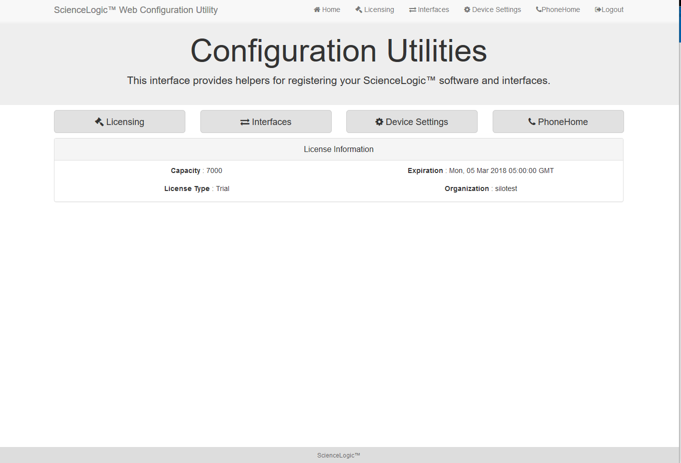
- After logging in, the main Configuration Utility page appears:
In version 11.2.0, the Licensing pages were removed from the Web Configuration Utility.
Changing the Password for the Web Configuration Utility
You can change the password for the Web Configuration Utility.
NOTE: If you want to change the password for the Web Configuration Utility on all SL1 appliances, you must log in to the Web Configuration Utility on each appliance and perform the steps in this section.
NOTE: You cannot change the username for the Web Configuration Utility. The username remains em7admin.
To change the password for the Web Configuration Utility:
- Log in to the Web Configuration Utility. The Configuration Utilities page appears.
- Click the button. The Settings page appears.
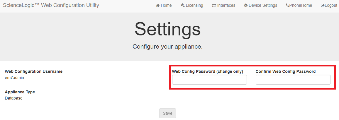
- In the Settings page, type the following:
- Web Config Password (change only). Type the new password.
- Confirm Web Config Password. Type the new password again.
- Click
- Perform steps 1-4 for each appliance for which you want to change the password for the Web Configuration Utility.
Licensing and Configuring a Database Server or All-In-One Appliance
The following steps are specific to appliances running versions of SL1 older than version 11.2.0.
If you are installing SL1 version 11.2.0, you do not need to license the Database Server. In version 11.2.0, the Licensing pages were removed from the Web Configuration Utility.
You must perform the following steps in the Web Configuration Utility to license an All-In-One Appliance or Database Server:
- Log in to the Web Configuration Utility. The Configuration Utilities page appears.
- Click the button. The Licensing Step 1 page appears.
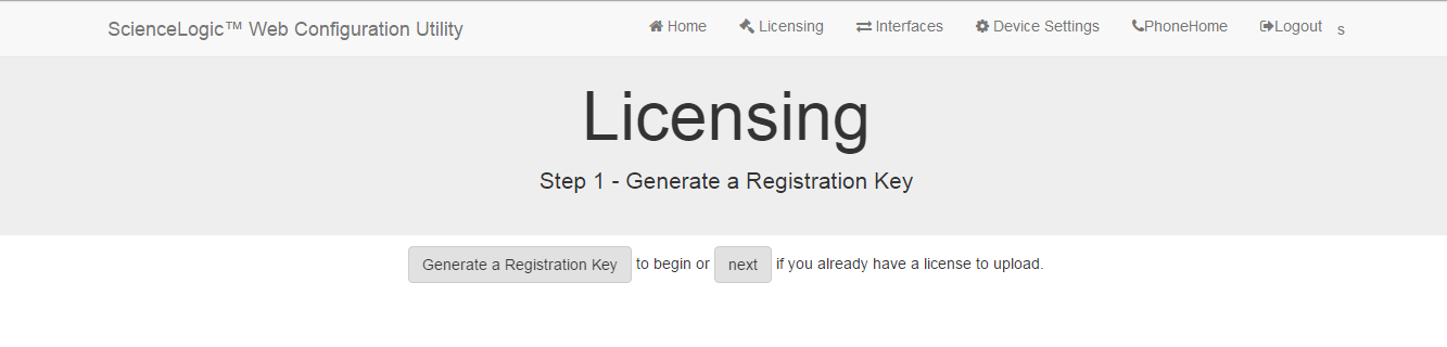
- In the Licensing Step 1 page, click the button.
- When prompted, save the Registration Key file to your local disk.
- Log in to the ScienceLogic Support Site (https://support.sciencelogic.com).
- Click your user name and from the menu select My Support and Customer Success.
- On the next page, click the button.
- Fill out the Appliance Information form and click the button.
- In the Upload Appliance Registration Key field, click thebutton and navigate to the file where you saved the Registration Key file.
- ScienceLogic Customer Support will generate a license for the All-In-One Appliance or Database Server.
- When you have the license for the All-In-One Appliance or Database Server, return to the Web Configuration Utility.
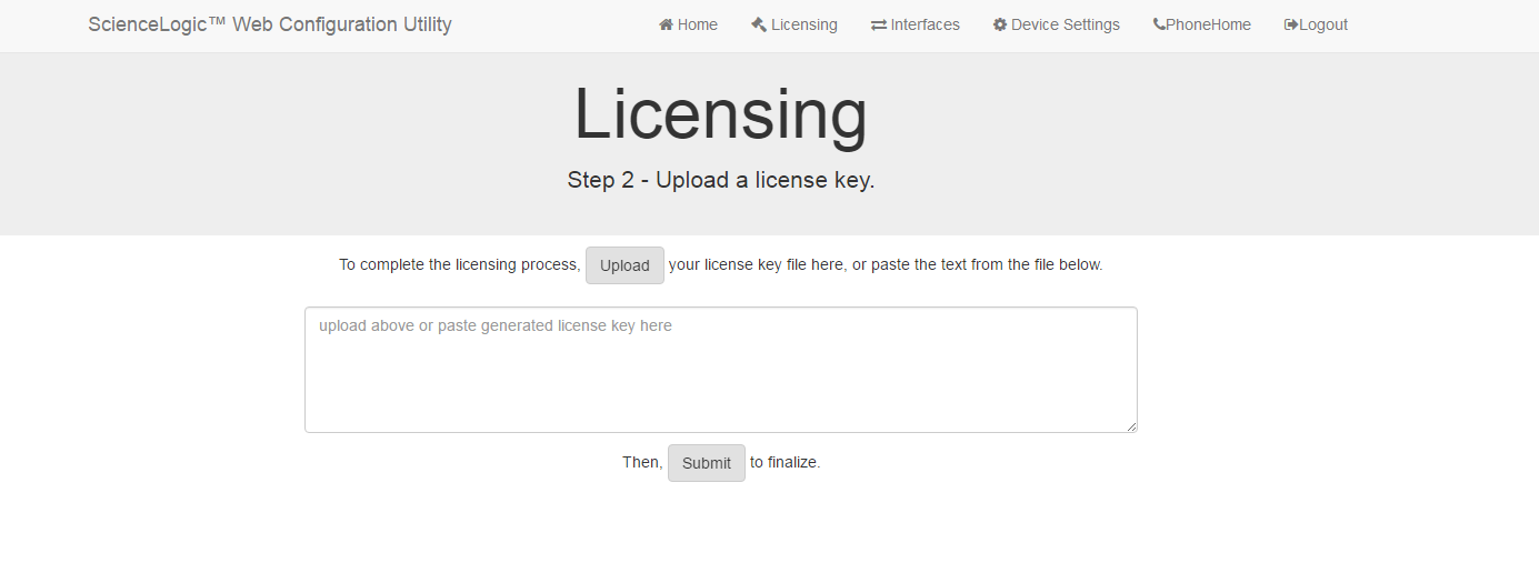
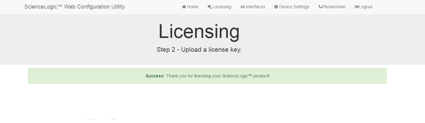
- In the Licensing Step 2 page, click the button to upload the license file.
- After navigating to and selecting the license file, click the button to finalize the license. If the license key is correct and has been saved successfully, the message "Success: Thank you for licensing your ScienceLogic product!" appears.
Configuring an Administration Portal
You must perform the following steps in the Web Configuration Utility to configure an Administration Portal:
The following steps are also relevant to appliances running SL1 version 11.2.0.
-
Log in to the Web Configuration Utility. The Configuration Utilities page appears.
-
Click the button in the upper-right of the page. The Settings page appears.

-
On the Settings page, enter the following:

- Database IP Address. The IP address of the primary ScienceLogic Database Server.
- For an All-In-One Appliance with multiple Administration Portals, enter the IP address for the All-In-One Appliance.
- If the Administration Portal and Database Server are AWS instances, supply the private IP address for the Database Server. To find the private IP of an AWS instance, go to AWS, go to the Instances page, and highlight an instance. The Description tab in the lower pane will display the private IP.
- Database Username. Username for the database account that the Administration Portal will use to communicate with the Database Server.
- Accept the default values in all other fields.
- Click the button. You may now log out of the Web Configuration Utility.
- In SL1, go to the Appliance Manager page (System > Settings > Appliances).
- Supply values in the following fields:
- Host Name. Enter the hostname of the Administration Portal, where relevant.
- IP Address. Enter the IP address of the Administration Portal.
- Model Type. Select Administration Portal [3] from the drop-down list.
- Description. Enter a description of the Administration Portal. This field is optional.
- Click the button. If the save is successful, the message "Appliance Registered" appears.
- If you are using an AWS RDS system, select the wrench icon (
 ) for the newly created Administration Portal. Supply values in the DB User field and the DB Password field.
 - If all information is valid and the Database Server can communicate with the Administration Portal , the appliance page will display "Yes" in the Validated column. If the Validated column displays "No" for longer than five minutes, double-check your settings and network connection.
Configuring a Data Collector or Message Collector
NOTE: The instructions for configuring a Data Collector or Message Collector for PhoneHome configuration differ from the instructions in this section. For details on configuring a Data Collector or Message Collector for PhoneHome configuration, see
If you are configuring a Data Collector or a Message Collector using SL1 version 11.2.0 or later, skip the procedures in this section and go to Installing and Configuring an SL1 Collector.
You must perform the following steps in the Web Configuration Utility to configure a Data Collector or a Message Collector:
- Log in to the Web Configuration Utility on the Data Collector or the Message Collector. The Configuration Utilities page appears.
- Click the button. The Settings page appears.
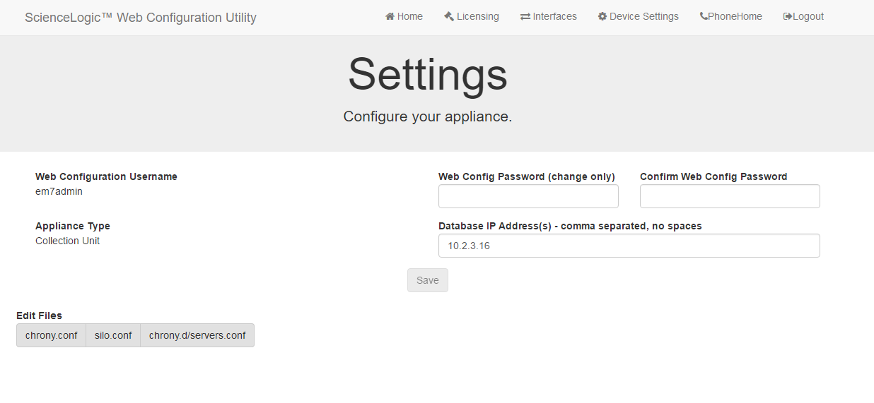
- In the Settings page, update the following field:
- Database IP Address. The IP address of the ScienceLogic Database Server(s). If more than one Database Server will manage this appliance, type the IP addresses of the Database Servers, separated by commas. If the Data Collector or the Message Collector and the Database Server are AWS instances, supply the private IP address for the Database Server. To find the private IP of an AWS instance, go to AWS, go to the Instances page, and highlight an instance. The Description tab in the lower pane will display the private IP.
- Click the button. You may now log out of the Web Configuration Utility.
- Perform these steps for each Data Collector and Message Collector in your PhoneHome configuration.
Registering the Data Collector or Message Collector with the Database Server
After configuring a Data Collector or Message Collector in the Web Configuration Utility, you must register the appliance with the main Database Server in your SL1 system.
To register a Data Collector or Message Collector with the main Database Server, perform the following steps:
- In the address bar of your browser, type the IP address of the SL1 appliance that provides the user interface for your SL1 system. The user interface is provided by either the Database Server or an Administration Portal. The login screen appears.
- Log in as the "em7admin" user with the password "em7admin".
- If this is your first successful login, you will be asked to agree to the End-user License Agreement. Read the End-user License Agreement then click the button.
- Go to the Appliance Manager page (System > Settings > Appliances):
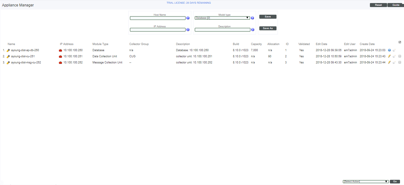
- Supply values in the following fields:
- Host Name. Enter the hostname of the Data Collector or Message Collector.
- IP Address. Enter the IP address of the Data Collector or Message Collector. If the Data Collector or the Message Collector are AWS instances, supply the private IP address for the Data Collector or the Message Collector. To find the private IP of an AWS instance, go to AWS, go to the Instances page, and highlight an instance. The Description tab in the lower pane will display the private IP.
- Model Type. If you are configuring a Data Collector, select Data Collection Unit [5] from the drop-down list. If you are configuring a Message Collector, select Message Collection Unit [6] from the drop-down list.
- Description. Enter a description for the Data Collector or Message Collector. This field is optional.
- Click the button. If the save is successful, the message "Appliance Registered" appears.
- If you are using an AWS RDS system, select the wrench icon () for the newly created Data Collector or Message Collector. Supply values in the DB User field and the DB Password field.

- If all information is valid and the Database Server can communicate with the Data Collector or Message Collector, the appliance page will display "Yes" in the Validated column. If the Validated column displays "No" for longer than five minutes, double-check your settings and network connection.
Defining the Syslog Server
For each device except for Message Collectors and All-In-One Appliances, you must specify the IP address of the server to which the SL1 appliance will send syslog messages. Enter the IP address of the syslog server that will monitor this SL1 appliance. Usually, this is the IP address of a Message Collector, Data Collector, or All-In-One Appliance.
NOTE: A device configured with Transport Layer Security (TLS) support for an rsyslog server can successfully exchange messages with a SL1 appliance configured with TLS support for an rsyslog client.
To specify the syslog server:
- Either go to the console of the SL1 appliance or use SSH to access the server.
- Log in as user em7admin with the password you configured during setup.
- Install the required Transport Layer Security (TLS) certificates by typing the following lines at the shell prompt:
mkdir -pv /etc/rsyslog.d/keys/ca.d
cd /etc/rsyslog.d/keys/ca.d/
NOTE: You might need to create a ca.d directory to contain the certificates needed for TLS encryption.
- To define the syslog server, type the following at the shell prompt:
sudo vi /etc/rsyslog.d/siteconfig.conf
- On a line of its own, add the following entry:
facility.priority@ip address of syslog server
where:
- facility specifies a valid facility value. These categories provide a general description of the originator of the message.
- priority specifies a valid priority value. These values specify severity.
- ip address of syslog server specifies the IP address of the syslog server that will monitor this SL1 appliance, usually a Data Collector or Message Collector.
NOTE: For details on valid facility and priority values, see https://docs.oracle.com/cd/E37670_01/E36387/html/ol_log_sec.html.
- Save your changes and exit the file (:wq).
- At the command line, type the following:
sudo service rsyslog restart
- Repeat steps 1-7 on each SL1 appliance in your system.
Defining the NTP Server
By default, SL1 uses the time servers in the Red Hat Linux pool of time servers. If you want to use a different time server, you can edit the configuration files for the time server.
From the Device Settings page of the Web Configuration Utility, you can edit the following time server files:
- chrony.d/servers.conf. This configuration file contains additional settings for the various chrony time servers.
- chrony.conf. This configuration file contains settings related to the time server (chrony.d) used by SL1.
To configure a time server file:
- Log in to the Web Configuration Utility. The Configuration Utilities page appears.
- Click the button. The Settings page appears.
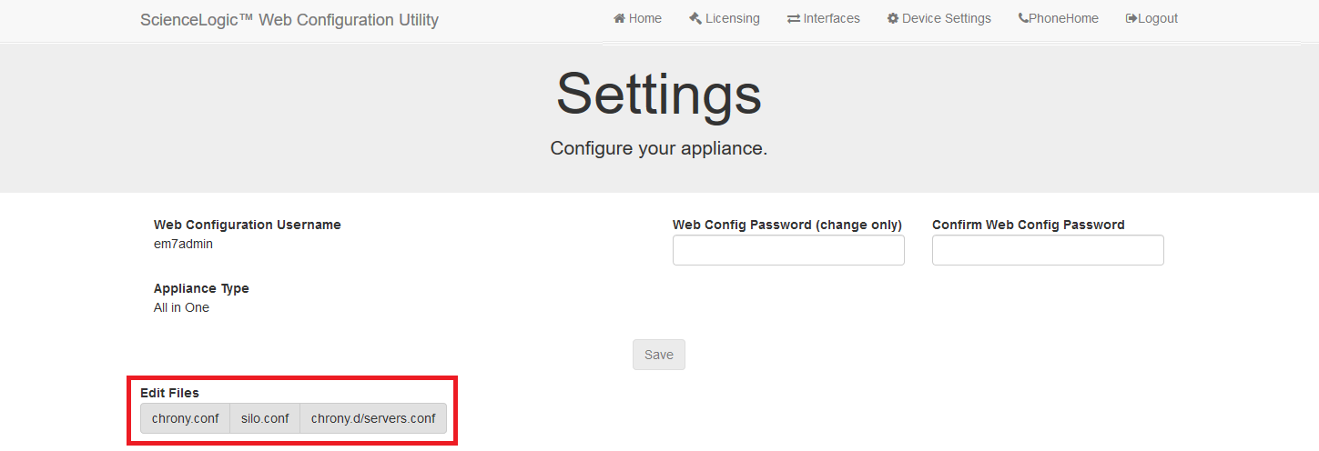
- In the Edit Files section, click chrony.d/servers.conf. The Chrony.d/servers.conf Editor modal page appears:
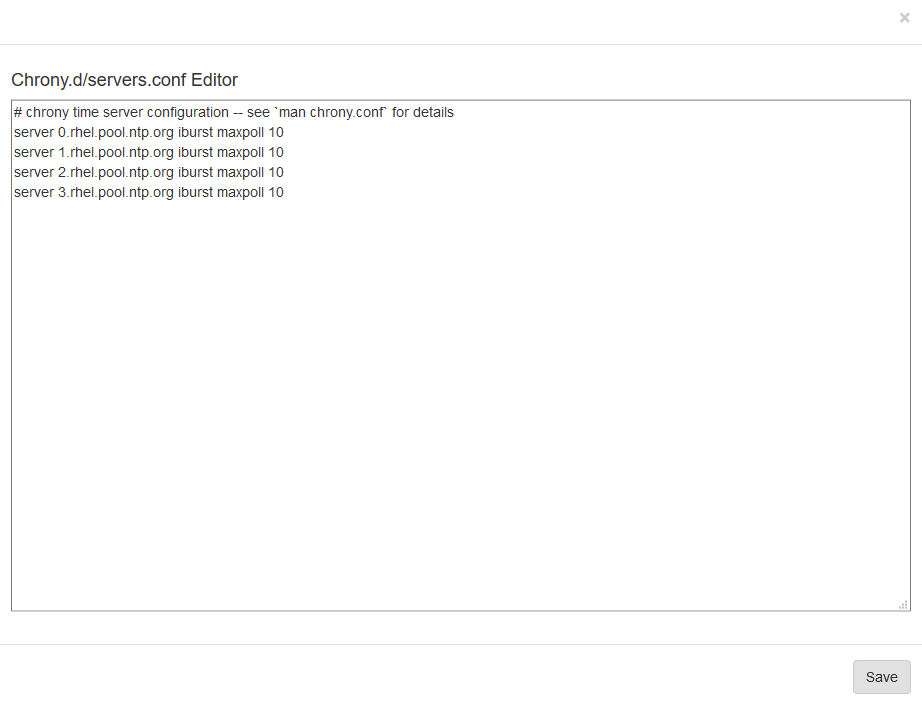
- In the Chrony.d/servers.conf modal page, copy the first line that begins with server, such as server 0.rhel.pool.ntp.org iburst maxpoll 10.
- Paste that line above the first line that begins with server.
- Replace the hostname portion of the line with the IP address or fully qualified domain name of your preferred time server.
- You can delete the additional lines or leave them as additional time servers.
- To save your changes, click Save and then close the modal window.
- If you need to configure the time server (chrony.d) used by SL1, click chrony.conf in the Edit Files section of the Settings page.
Creating a Bonded Interface
A bonded interface (also known as port trunking, channel bonding, link aggregation, and NIC teaming) allows you to combine multiple network interfaces (called "slave interfaces") into a single logical interface (called a "master interface"). A bonded interface can:
- increase available bandwidth
- provide redundancy
To the operating system, a bonded interface appears as a normal network interface. However, the bonded interface uses a round-robin protocol to assign network traffic to the slave interfaces that make up the bonded interface.
To create one or more bonded interfaces:
- Log in to the Web Configuration Utility. The Configuration Utilities page appears.
- Click the button. The Interfaces page appears.
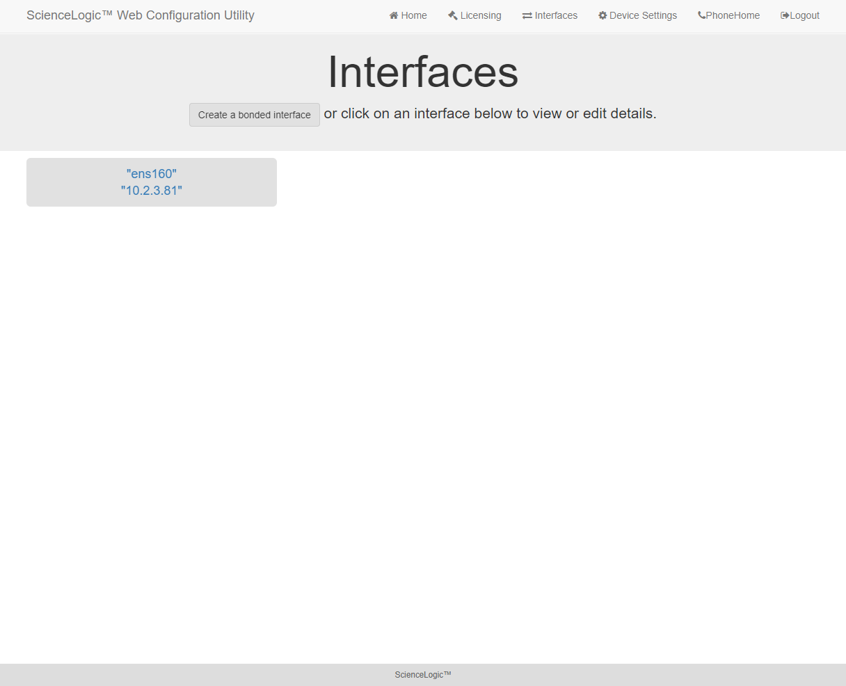
- In the Interfaces page, click the button. The Create a Bonded Interface page appears.
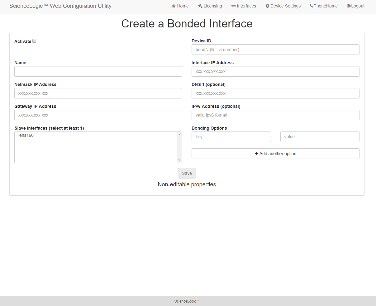
- In the Create a Bonded Interface page, enter the following:
- Device ID. Required. ID for the bonded interface. Enter a string with the format:
bondN
where N is a number. For example, you could enter bond0, bond1, or bond64.
If the device ID already exists in the SL1 System, the SL1 system will display an error message.
- Name. Required. Enter a user name for the bonded interface.
- Interface IP Address. Required. Enter the IP address for the bonded interface in standard IPv4, dotted-octet format.
- Netmask IP Address. Required. Enter the netmask for the bonded interface in standard IPv4, dotted-octet format.
- Slave Interfaces. Required. Select one or more interfaces from the list of available interfaces. The selected interfaces will be used by the new bonded interface.
- DNS1. Optional. Enter the IP address of the DNS server that the bonded interface will use. Enter the IP address in standard IPv4, dotted-octet format.
- Gateway IP Address. Optional. Enter the IP address of the gateway device or router that the bonded interface will use. Enter the IP address in standard IPv4, dotted-octet format.
- IPv6 Address. Optional. Enter the IP address for the bonded interface, in IPv6 format.
- Bonding Options. Optional. You can enter one or more bonding options. For each option, enter the name of the option in the key field and the value in the value field.
For details on bonding options, see the Red Hat documentation on Bonding Interface Parameters: https://access.redhat.com/documentation/en-US/Red_Hat_Enterprise_Linux/6/html/Deployment_Guide/sec-Specific_Kernel_Module_Capabilities.html#s3-modules-bonding-directives
Defining a Proxy Server
A proxy server enables SL1 appliances to get system updates when the appliance does not have a direct connection to the internet. A proxy server also enables ScienceLogic Database Servers to send subscription licensing data to ScienceLogic.
Each SL1 appliance can define its own proxy server.
To define a proxy server:
- Go to the Appliance Manager page (System > Settings > Appliances).
- Find the appliance for which you want to define a proxy server. Click its toolbox icon (
 ).
). - When prompted to enter your username and password, log in as the "em7admin" user with either the default password of em7admin or the password you configured.
- After logging in, the main Configuration Utility page appears:
- Click the button. The Settings page appears.
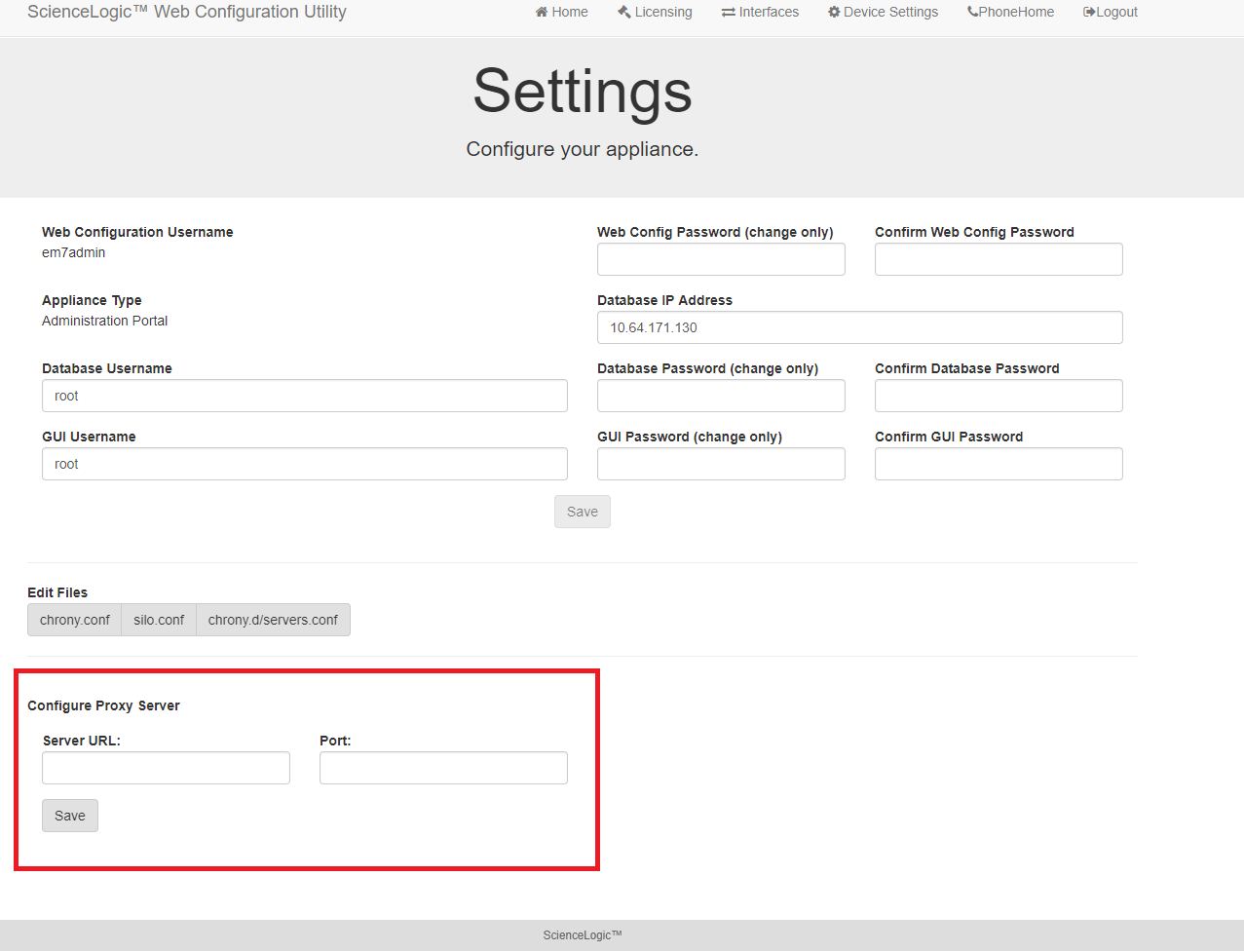
- Enter values in the following fields:
- Server URL. Type the URL of the proxy server. For example, "http://10.2.12.51".
- Port. Type the port on the proxy server to which the SL1 appliance will talk.
- Click .