![]()
Use the following menu options to navigate the Skylar One user interface:
- To view a pop-out list of menu options, click the menu icon (
 ).
). - To view a page containing all of the menu options, click the Advanced menu icon (
 ).
).
What is a Map?
A map is a visual representation of the various devices and related elements, also called nodes, in your environment that have been discovered by Skylar One. A map displays the important details about the nodes, their hierarchy, and the relationships associated with those nodes. In Skylar One, maps are rendered using HTML5.
Maps can display business services, component maps (DCM, DCM+R), CDP topology, LLDP topology, Layer-2 topology, Layer-3 topology, and Virtual Infrastructure (VMware and virtual machines). You can also create your own maps with your most important devices, and add images, text, and shapes to customize your maps.
To view a map, go to the Maps page (![]() ) and click the name of the map from the Maps page. The following is an example of a map that displays business services:
) and click the name of the map from the Maps page. The following is an example of a map that displays business services:

A map includes the following graphical elements:
- Nodes. Nodes are shapes that represent Devices, Topology Elements, and Business Services defined in Skylar One. The shape of a node represents its type, and the color of its outline specifies the current state of the node.
- Links. Also called "edges", links are lines with or without arrows that represent the relationships and hierarchies between nodes. All device relationships are displayed as child and parent relationships. If the nodes on a map contain arrows, then the arrows represent the direction of the relationship, pointing from the child node to its parent node. If a node does not contain an arrow, then the relationship is bi-directional, or undirected.
For more information, see Viewing a Map.
What is a Classic Map?
A Classic Map is the same as a View in the classic user interface.
A Classic Map (View) is a graphical representation of a group of devices. The Classic Maps page (Maps > Classic Views, formerly the tab in the classic user interface) allows you to view and edit maps and relationships between devices and virtual infrastructure. In Skylar One, views are organized by device group, organization, device category, component maps, Layer-2 topology, CDP topology, LLDP topology, Layer-3 topology, or Virtual Infrastructure (VMware and virtual machines).
In the classic user interface only, you can also create your own classic maps with your most important devices, and add images, text, links, and shapes to customize your maps.
To navigate to the Classic Maps page, go to Maps > Classic Maps (or the tab in the classic user interface). For more information, see Viewing the Classic Maps Page.
The following is an example of an HTML5-based classic map from the Classic Maps page in Skylar One:
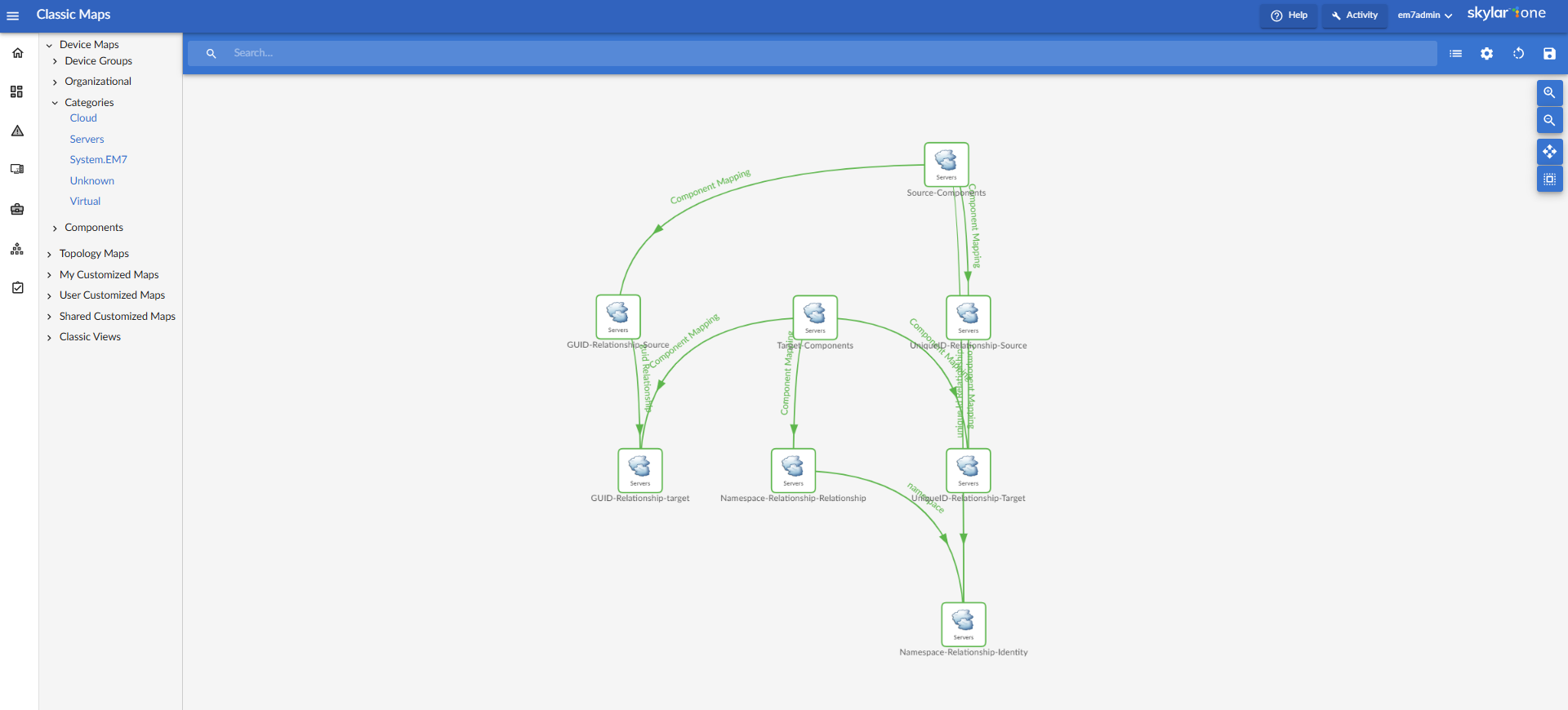
For additional information about classic maps or views, see the
Topology Maps
During discovery, Skylar One automatically discovers all networks and subnets in your infrastructure. On the Classic Maps page (Maps > Classic Maps), Skylar One creates graphical representations of these discovered networks and subnets to create topology maps.
Skylar One creates four types of topology maps, which are described in the following sub-topics:
You can also view and create maps containing all four topology types on the Maps page.
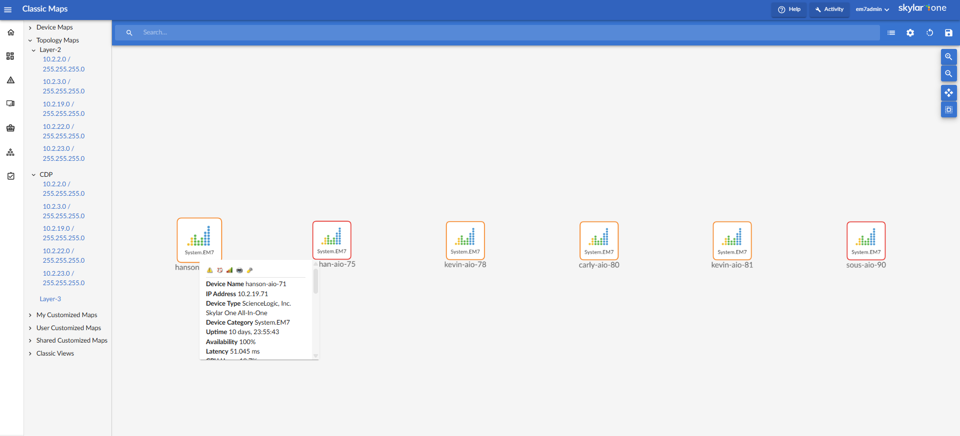
To view the properties for a node on a classic map, hover over that node.
Layer-2 Maps
Layer-2 networks are unrouted subnets, where devices are identified by MAC addresses, as opposed to routed networks, where devices are identified by IP address. Layer-2 links communicate over the Data Link Layer and use Ethernet and MAC addresses to communicate with devices in the same LAN or WAN.
Standard Layer-2 processing, which is used by default in versions of Skylar One prior to 12.5.1, uses the "Enterprise Database: Topology Crunch" process to determine Layer-2 topology relationships based on device category, with the purpose of connecting network devices to each other.
Enhanced Layer-2 processing, which is available in Skylar One 12.5.1 and later, can form Layer-2 relationships between any devices that match a MAC address from the BRIDGE-MIB or sourced from Dynamic Applications, regardless of device category.
The Layer-2 Maps page (Maps > Classic Maps > Topology Maps > Layer-2) displays a network map, where you can view details and relationships in any layer-2 network that has been discovered by Skylar One:
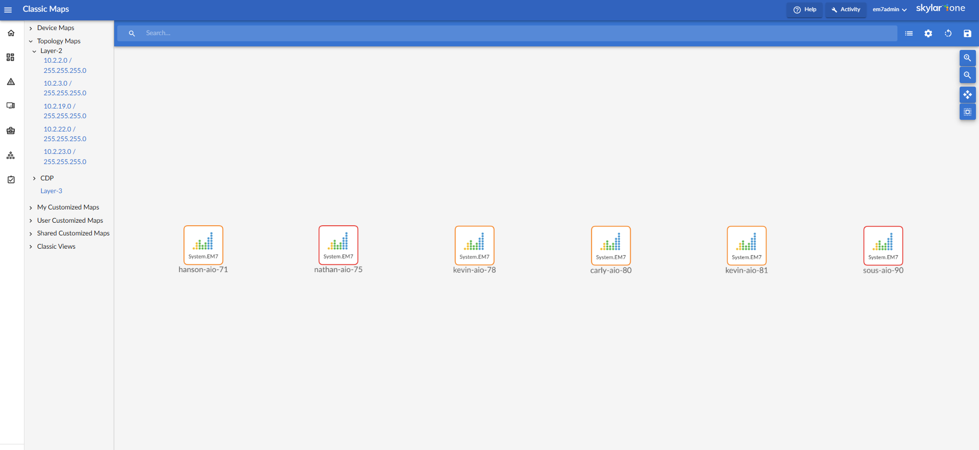
A layer-2 network map can include:
- Devices of each device category defined in Skylar One.
- Unknown devices are represented with cloud icons and labeled as "unknown".
- Links between devices.
- Links between networks (created with switches or routers).
- Unknown connections are represented with cloud icons and labeled as "unknown".
- Skylar One automatically updates the map as new devices are discovered. Skylar One also updates the map with the latest status and event information.
CDP Maps
Cisco Discovery Protocol (CDP) allows discovery of Cisco hardware and allows Cisco hardware within the same LAN or WAN to share information about each other. This information includes the MAC address and IP address, the operating system, and information about the network interface. CDP is a Layer-2 protocol that uses the Data Link Layer and is unrouted. CDP can also run on legacy Hewlett Packard Hardware.
CDP maps show layer-2, unrouted subnets, where devices are identified by MAC addresses, as opposed to routed networks, where devices are identified by IP address.
Standard CDP processing, which is used by default in versions of Skylar One prior to 12.5.1, requires that both devices respond with CDP neighbor data, show each other as a neighbor, and be managed devices in Skylar One in order to form a CDP topology relationship with each other.
Enhanced CDP processing, which is available in Skylar One 12.5.1 and later, can form CDP relationships between two devices so long as at least one of those devices responds with CDP neighbor data and is a manged device in Skylar One. This process also supports asynchronous collection, which increases the scale of CDP collection when devices are slow to respond or to load due to network latency.
The CDP Maps page (Maps > Classic Maps > Topology > CDP) displays a network map, where you can view details and relationships in any CDP network that has been discovered by Skylar One:
For Skylar One to create CDP maps, you must first enable CDP collection and topology processing on the Behavior Settings page (System > Settings > Behavior). When you do so, Skylar One discovers CDP relationships where possible.
If you enable CDP collection and topology processing, Skylar One automatically discovers all CDP relationships in your infrastructure. Skylar One then creates graphical representations of those discovered networks and subnets. These graphical representations are called Topology Views.
A CDP map can include:
- Devices of each device category defined in Skylar One.
- Links between devices.
- Links between networks (created with switches or routers).
- Skylar One automatically updates the map as new devices are discovered. Skylar One also updates the map with the latest status and event information.
NOTE: Because CDP provides very accurate discovery details, links and relationships in CDP Maps take precedence over links and relationships in Layer-2 Maps.
To create a map that includes all CDP relationships, click on the Maps page and use the following advanced search criteria in the Search field: relationship has (type = 'CDP')
LLDP Maps
Link Layer Discovery Protocol (LLDP) allows discovery of Cisco hardware and allows Cisco hardware within the same LAN or WAN to share information about each other. This information includes the MAC address and IP address, the operating system, and information about the network interface. LLDP is a layer-2 protocol that uses the Data Link Layer and is unrouted.
LLDP maps show layer-2, unrouted subnets, where devices are identified by MAC addresses (as opposed to routed networks, where devices are identified by IP address).
Standard LLDP processing, which is used by default in versions of Skylar One prior to 12.5.1, requires that both devices respond with LLDP neighbor data, show each other as a neighbor, and be managed devices in Skylar One in order to form an LLDP topology relationship with each other.
Enhanced LLDP processing, which is available in Skylar One 12.5.1 and later, can form LLDP relationships between two devices so long as at least one of those devices responds with LLDP neighbor data and is a manged device in Skylar One. This new process also supports asynchronous collection, which increases the scale of LLDP collection when devices are slow to respond or to load due to network latency.
The LLDP page (Maps > Classic Maps > Topology Maps > LLDP [BETA]) displays a network map, where you can view details and relationships in any LLDP network that has been discovered by Skylar One.
NOTE: For Skylar One to create LLDP maps, you must first enable LLDP collection and topology processing on the Behavior Settings page (System > Settings > Behavior). When you do, Skylar One discovers LLDP relationships where possible.
If you enable LLDP collection and topology processing, Skylar One automatically discovers all LLDP relationships in your infrastructure. Skylar One then creates graphical representations of those discovered networks and subnets. These graphical representations are called Topology Views. The Maps > Classic Maps > Topology Maps pages allow you to view details and relationships in any network that has been discovered by Skylar One.
A LLDP map can include:
- Devices of each device category defined in Skylar One.
- Links between devices.
- Links between networks (created with switches or routers).
- Skylar One automatically updates the map as new devices are discovered. Skylar One also updates the map with the latest status and event information.
NOTE: Because LLDP provides very accurate discovery details, links and relationships in LLDP Maps take precedence over links and relationships in layer-2 Maps.
To create a map that includes all LLDP relationships, click on the Maps page and use the following advanced search criteria in the Search field: relationship has (type = 'LLDP')
Layer-3 Maps
Layer-3 networks are routed subnets, where devices are identified by IP address, as opposed to unrouted networks, where devices are identified by MAC address. Layer-3 links communicate over the Network Layer and allow devices from different subnets or networks to communicate. Layer-3 links use IP addresses to identify devices and their networks and therefore are routed and can pass messages through routers.
Skylar One creates Layer-3 maps by running traceroute from a Data Collector to all devices that have layer-3 collection enabled in the device class.
Standard Layer-3 processing, which is used by default in versions of Skylar One prior to 12.5.1, requires all the hops in a traceroute to respond and match devices within Skylar One. The traceroute is discarded whenever the system detects hops that fail to respond or the traceroute includes hops that do not match devices in Skylar One.
Enhanced Layer-3 processing, which is available in Skylar One 12.5.1 and later, does not discard incomplete traceroutes or results that include unmatched hops. Instead, the system will form relationships between any two hops that respond and match devices in Skylar One.
The Layer-3 Maps page (Maps > Classic Maps > Topology Maps > Layer-3) displays a network map, where you can view details and relationships between Data Collectors and layer-3 routers and switches, and between the layer-3 routers and switches that have been discovered by Skylar One.
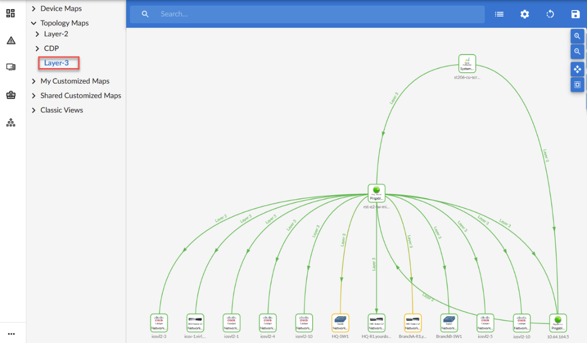
A Layer-3 network map can include:
- Data Collectors, switches, and routers.
- Links between devices.
- Links between networks (created with switches or routers).
- Skylar One automatically updates the map as new devices are discovered. Skylar One also updates the map with the latest status and event information.